Pipe Expansion Loop Design
Keywords
Summary
The purpose of this file is to illustrate quick sizing of the expansion loops.
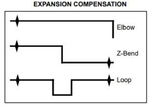
Pipe expands when heated and contracts when cooled. When a pipe allowed to move (unrestrained), it is free to expand or contract without generating thermal stresses. Once the pipe is restrained at the ends (by anchors or equipment nozzles), thermal stresses can be generated. These stresses are a result of a system’s lack of flexibility and ability to compensate for thermal expansion or contraction. Expansion compensation in the form of expansion loops, 90° elbows and z-bends are a simple, low cost and low maintenance design elements that can be used to increase system flexibility and decrease pipe stresses. These arrangements can be observer in Figure 1.
Hints
Share
Project/Case Example
Oxygen and Natural Gas supply lines to cutting tables.
On this project there was a 4” oxygen line and a 2” natural gas line that ran 286ft and 160ft in length respectively. Both these lines had a design temperature of 140°F and -40°F, resulting in 4” of thermal expansion in the oxygen line and 2.25” of expansion in the natural gas line. To overcome this expansion, a couple methods were used and utilized.
Both lines had to run vertically from near grade for approximately 28’ before a 90 degree change in direction. This change in direction allows for some thermal expansion compensation as can be seen on Figure 1.
The Oxygen line then ran straight for approximately 282’, and natural gas line ran for approximately 157’. Due to lengths of these long straight segments of pipe, expansion loops were required to be added to compensate for thermal expansion.
Both lines then ran back down to grade taking advantage of 90° changes to get down to grade and into building mirroring elbow and z-bend patterns in Figure 1. The material used for this case was carbon steel.
The calculations for this process in the project were followed in as detailed in the Solutions/Best Practices section of this document.
Figure 1
Codes and Standards: ASME Piping Codes B31.1, B31.3
Solution/Best Practice
1. Calculate the expansion (or contraction) in the pipe.
The first step in sizing an expansion loop is to calculate the thermal expansion of the pipe run. The sizing of the expansion compensation (loops) may be done by the use of simplified equations, nomograms or tables.
The first step in sizing the loop is to calculate piping expansion Δ.
Δ =α lo( Tf-To)
Where:
α is material’s linear thermal expansion coefficient, in/in°F (this value can be found in tables in B31.1/B31.3 for a specific material. i.e. carbon steel, stainless steel, etc.)
lo is original pipe length, ft
To is initial temperature, °F
Tf is the final temperature °F.
The thermal expansion coefficient α is provided in appendices of the piping codes ASME B31.1 and ASME B31.3.
Many manufacturers provide tables or on-line calculators that allow to find thermal expansion of a pipe material, see section References below.
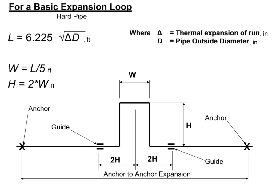
2. Sizing expansion compensation by simplifying equations
Figure 2
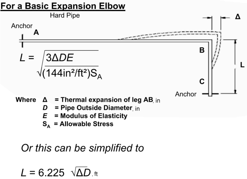
Figure 3
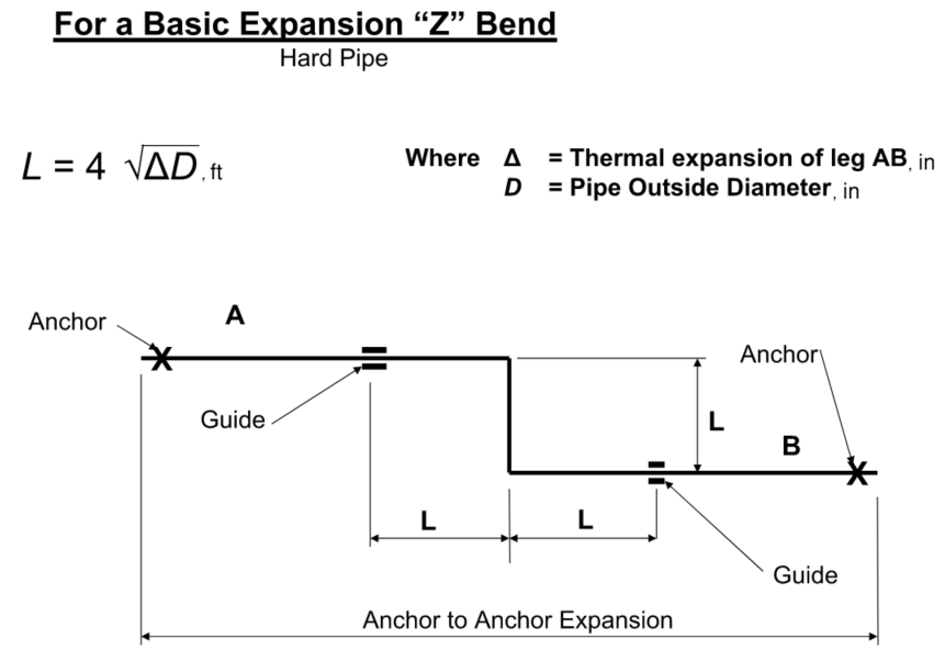
Figure 4
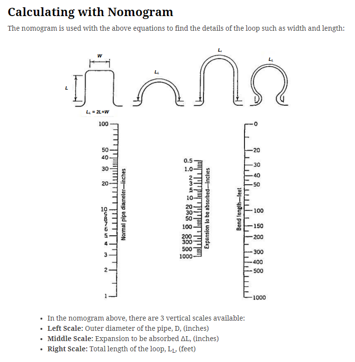
3. Sizing expansion compensation by using nomogram
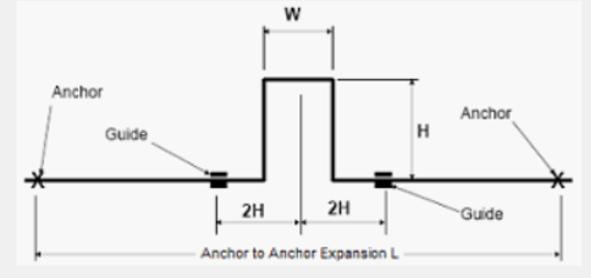
The total loop length LL = W +2L
Loop width W = LL / 5
Loop length L = 2W
Figure 5
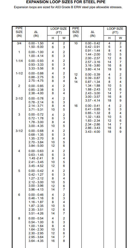
4. Sizing loops from tables
Based on the expected expansion and pipe diameter, select loop size using this figure.
Figure 6
5. Required pipe support arrangement
The types of supports must be considered whenever routing the expansion loop. As a guideline, for standard gravity support (resting support, pipe shoe), follow standard support spacing based on the line size (using ASME B31.1 spans, or project specific span tables.)
Based on the type of expansion loop used, the placement of guides and anchors/fixed supports must follow the arrangements outlined in these figures:
Figure 7
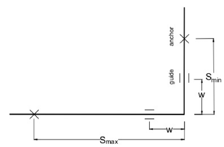
Figure 8
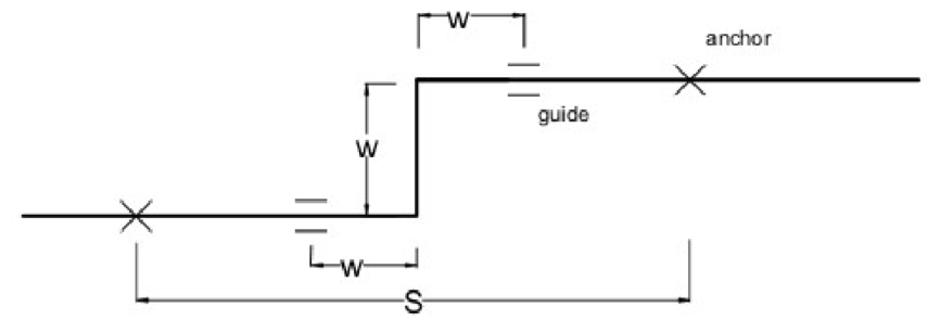
Figure 9
6. Guidelines for the expansion loops design
- Try to locate the expansion loop in the center of the distance between two anchors. The symmetrical loop is more effective then asymmetrical loops as they reduce stress equally from both sides.
- Asymmetrical loops can be used in situations where the available space on site is not at the midpoint of the pipe run. Size that type of the loop based on “elbow” type based on the thermal expansion of the longer segment.
- Loops on many parallel pipes on pipe rack can be nested inside each other to utilize space efficiently. Always check expansion of each pipeline to avoid clashes at pipe loops location.
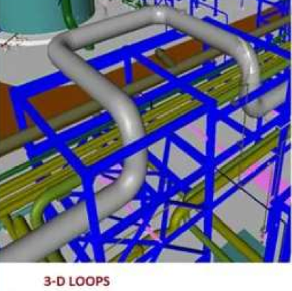
- 3D loops can be used to prevent possible conflict with other lines.
Figure 10
- Typical dimension between the loop anchors is 70ft (max 100ft). A spool longer than 100ft might not be practical because:
- Friction of the pipe supports might prevent loop “spring”
- Displacement due to expansion might be large enough to cause a support to slide off the;
- Supporting steel; support could slide off the steel due to hydraulic pressure at start-up.
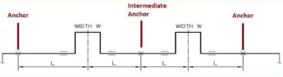
- Intermediate anchors (limit stops) may be used to divide segment and use multiple loops absorb the thermal growth.
Figure 11
- Remember to install low point drains if a loop is directed down (especially for steam & condensate lines).
- There are some cases, where stress analysis using programs like Caeser II would be recommended (I.e. steam, and large pipe diameters).
References
- https://www.engineeringtoolbox.com/steel-pipe-expansion-loop-d_1069.html
- Thermal Expansion Calculator | Good Calculators
- Pipe Expansion Thermal Loop Equations and Calculator (engineersedge.com) https://engineersedge.com/calculators/pipe_expansion_thermal_loop_15035.htm
- Technical Data, Calculation and Design, 103-4_001.pdf (thermacor.com)
- Steel Pipes – Calculate Thermal Expansion Loops (engineeringtoolbox.com),
- Expansion-loop-for-Thermal-Expansion-of-pipes.flow.pdf (maplesoft.com)
Engineering success.
JNE Consulting is here to help. Contact us today at info@jnegroup.com.